


Case Study: Upper Neuadd Reservoir for Dwr Cymru Welsh Water, Powys
Upper Neuadd reservoir is the first in a series of three reservoirs in cascade, lying upstream of Lower Neuadd and Pontsticill reservoirs. Construction of the dam was completed in 1902 to supply the local water undertaking, Merthyr Tydfil Waterworks the reservoir now serves primarily to provide flood storage.
 The dam was Grade II* listed in July 2005 ‘for its special interest as an architecturallydesigned dam of spectacularly massive construction and definite character’.
The tower superstructure (that previously housed a back-flow flushing tank to keep the draw off screen clear) above the valve shaft, has given rise to concerns and also internally.
A major collapse of the upstream part of the tower could cause major damage to the current low-level overflow arrangements that are located directly upstream of the tower and shaft.
Cintec International Ltd were invited to tender by Welsh Water based on a design developed in conjunction with Arup of Cardiff for the “design, supply and installation of cementitious anchors necessary to repair and maintain the structural integrity of the valve tower at the Upper Neuadd Reservoir. This will include all horizontal, vertical and consolidation anchors in either the temporary or permanent condition.”
Objective:
The objective of the works was to ensure the structural integrity of the valve tower for the foreseeable future. The valve tower comprised limestone masonry typically 610mm thick. It should be noted that the coins, which are triangular in plan, were considerably thicker. There appeared to be 2 skins of dressed stone with random stone infill.
The anchor design had to address the following issues:
-
- Stabilization of the tower roof including any necessary horizontal and consolidation anchors.
- Provision of all anchors necessary to resist thrust forces where the roof meets the vertical structure.
- Provision of all anchors to withstand the wind loads.
- Provision of all anchors necessary to resist the seismic loads.
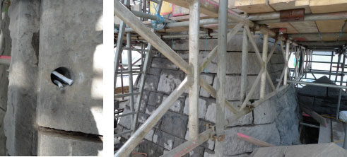 Views of pinnacle section; left drilling vertically through the structure. Right: general areas of pinnacle consolidated with anchors. The consolidation anchors were a mix of 10mm and 12mm diameter in 32mm and 40mm holes. Th vertical anchors were 24mm diameter pre-stressed in a 66mm hole. Horizontal anchors were a mix of 24mm in 66mm holes and 20mm anchors in 52mm holes. The limestone masonry was particularly hard to drill and prevailing weather conditions often severe cold and wind. As built drawings for half elevations are shown below.