
SECTION 1: ENGINEERING SURVEY AND DESIGN
INTRODUCTION
This briefing note describes the overall process from receipt of initial enquiry through to installation of the strengthening system.
OUTLINE DESIGN PRODUCTION
Information sent by the Client (such as Principal Inspection Report, Assessment Report, photographs and drawings) is used to produce an outline design, detailing the required anchor sizes and lengths. This requires some preliminary calculations using a modified mechanism analysis to determine the amount of reinforcement required. Numerous factors must be considered in the outline process to achieve a cost effective and efficient design that will achieve the required specification. A typical outline design arrangement is shown in Figure 1:
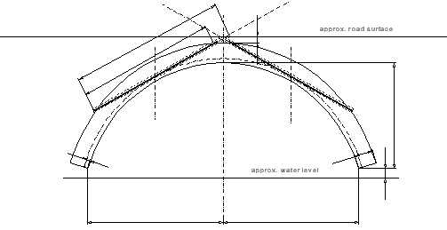
Figure 1.1 A typical Archtec design arrangement
This information, along with any other relevant engineering details, is sent to Cintec™ for costing. The design is then proposed to the Client for consideration.
INSPECTION AND SURVEY
Once a contract has been awarded a detailed survey of the bridge is required. A total station survey of the whole bridge is undertaken, paying particular attention to the road and barrel surfaces. In addition, Control Points are established that are used for the setting out of the drilling rig during the works. These points are positioned in the road surface when installation is from above and in the barrel intrados surface when installation is from below.
During the survey a visual inspection is also carried out to determine the general condition of the bridge and to note any specific defects that may influence the design. Where necessary, locations of defects such as cracks will be included in the survey. If the barrel thickness has not been determined previously, or if there is any reason to doubt the information already available, then it may be necessary to arrange for core samples to be taken. Other internal investigations may be necessary for example; to determine whether backing exists; establish the thickness of concrete saddles and also to locate underground services.
GEOMETRY MODELLING AND SETTING OUT
Using the data from the survey a 3-dimensional CAD model is generated, including the road and barrel surfaces and Control Points.
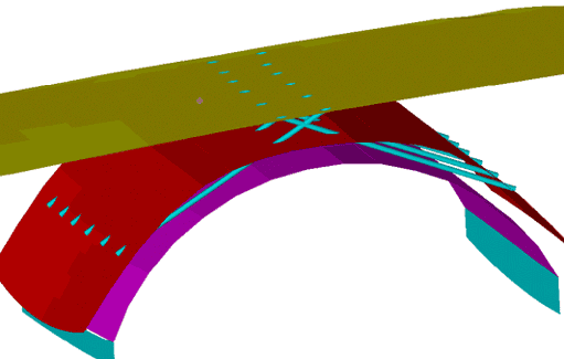
Figure 3.1 A 3-dimensional CAD model of a typical Archtec bridge
Anchors are positioned in the model as required and the intersections of the holes with the road determined to define the setting out locations for drilling (Figure 3.1). Dimensions from the Control Points, vertical angles and horizontal angles, are calculated to describe the holes that have to be drilled precisely.
NUMERICAL ANALYSIS
The detailed calculations for the Archtec design are carried out using the program ELFEN that uses the Discrete Element technique. The discrete element technique is well suited to simulation of non-homogenised continuum such as masonry, concrete and soil. By representing separate parts that can deform and interact with each other highly dynamic and non-linear systems both in 2D and 3D can be modelled more simply at a fundamental level. Many thousands of parts can be represented each with prescribed friction/contact laws at their boundaries. The capability to evolve further parts by fracturing into separate fragments is also possible by using limiting tension non-linear material models and advanced mesh adaptivity schemes. Efficient solvers based on explicit dynamic algorithms enable many classes of problem to be solved that would be near impossible by conventional analysis.
The arch is modelled in two dimensions using an appropriate section (or sections) from the 3D CAD model. The properties of the materials and the behaviour of the material contacts are defined from the information collated for the structure. Where necessary, when considering the analysis parameters, comparisons can be made with full-scale tests. The loading is applied in accordance with BD 21/97, including factors for lift-off and centrifugal effects if required.>
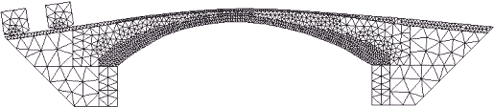
Figure 4.1 A discrete element model of an Archtec bridge
Initially the existing structure is analysed without any anchors, and it is sometimes possible that sufficient additional strength can be justified on the basis of the advanced analysis and that the need for strengthening can be avoided. Assuming, however, that the structure fails then the arrangement of anchors will be included in the model and the structure assessed at Ultimate Limit State for the required loading. This is normally done for 40 tonne single, double and triple axles but other live load ratings can be considered. Stresses in the masonry are examined and the axial loads and bond stresses in the anchors checked. The analysis is also carried out at Serviceability Limit State to check that no permanent damage has occurred (eg deformation of the arch barrel or slipping of the anchors). Calculations summarising the parameters used in the analysis and the results obtained can be provided for the client if required.
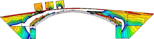
Figure 4.2 Stress contour results for an Archtec bridge
DRAWING PRODUCTION
A General Arrangement drawing and a Setting Out drawing are produced providing the details of the anchor arrangement. The General Arrangement shows the approximate dimensions of the bridge and the positions of the anchors in plan and elevation. The Setting Out drawing contains the details of the Setting Out Points and their distances from the Control Points. It also lists the final anchor and hole lengths with their respective angles of installation. If remedial measures are required in addition to the Archtec system then they may be included on the General Arrangement drawing or on separate drawings.

Figure 5.1 A typical Archtec General Arrangement drawing
CONSTRUCTION PHASE
The strengthening method relies on very precise alignment of the holes drilled into the structure. The accuracy of the angle and position are crucial as the hole can be as little as 30mm away from the arch soffit at the tangent location. Close cooperation between Gifford and Partners and the drilling contractors has been necessary to develop the appropriate setting out and work procedures in order to achieve the required standards, and only a small number of approved contractors are used for the work.
At the beginning of the contract phase the drilling contractors have to mark out the Setting Out Points and locate any services in the bridge that may clash with the anchor installation (Figure 6.1). A representative from the engineers or Cintec™ assists with this process and liaises with the designers should adjustments to the design be necessary.
With the drilling points defined and services exposed, the drilling contractor can set up the drilling rig on the road surface touching the road at the defined point of contact (Setting Out Point). The rig is bolted to the road through the tarmac to prevent movement during drilling. The vertical angle, as defined on the Setting Out Drawing, is set and drilling commences (Figure 6.2). During drilling the angle is checked on several occasions to ensure that the drilling rig has not deviated. The accuracy of the angle and position are crucial as the hole can be as little as 30mm away from the arch soffit at the tangent location.
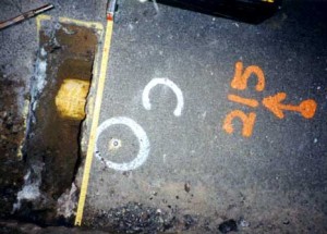
Figure 6.1 Anchor setting out and exposure of buried services
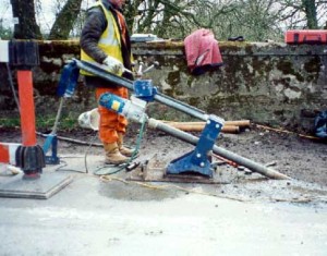
Figure 6.2 Drilling of holes for Archtec anchors
Once the hole is drilled, the anchor and sock is inserted into the hole (Figures 6.3 and 6.4). and the drilling rig can then be moved to begin the next hole. The grout is injected through the grout tubes to the bottom of the sock, which inflates from the bottom up thus preventing air from becoming trapped. The grout pressure expands the sock to fill the hole, providing a bond between the grout and masonry but not allowing the grout to leak through the masonry. A model of the Cintec™ anchor is shown in Figure 6.5. As the grout cures the anchor/grout/masonry bond is completed and the road surface can then be made good. This process is repeated for all the holes detailed on the construction drawings.
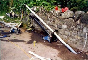
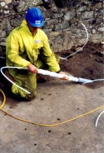
Figures 6.3 and 6.4 Insertion of Cintec™ anchor into drilled hole
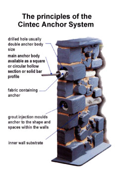
Figure 6.5 Cintec™ anchor detail
SECTION 2: RAILTRACK PROTECTION METHOD
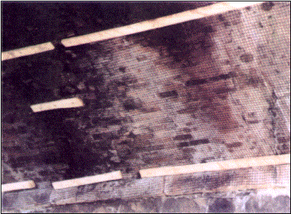
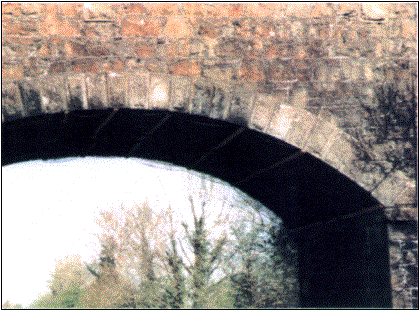
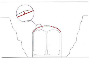
The following photographs show the protection system that was used on a previous project and the diagram illustrates the principle.
Netting (normally Fortrac), small enough to prevent any tiny fragments falling to the line but strong enough to secure any larger particles, is fixed to the surface of the arch by battening secured by screws into the arch soffit.